
Introduction
In a typical closed-loop, or feedback, control of a machine or a process, the controller compares the actual sensor measurement with the desired value and then adjusts the signal to the actuator accordingly. The actuator converts signals into a physical quantity to initiate a motion, thereby regulating the controlled variable. In general, actuators are classified into four categories: electric, pneumatic, hydraulic and magnetic.Magnetic Actuators
Magnetic Actuators
Magnetic actuators are the actuators that use magnetic fields to produce motion. Thus magnetic actuators convert input electrical energy into magnetic energy which creates a magnetic force to produces mechanical motion over a limited range.

Electric Actuators
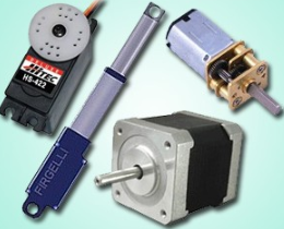
Electric actuators convert electric power into mechanical power. Electric actuators are available in one of two types, direct current (DC) and alternating current (AC). AC induction and synchronous motors are ideal for constant speed applications with little load variations. AC motors use line current to directly provide more power compared to DC motors of similar size. For position and speed control applications involving variable loads, DC motors are favored. DC motors fall in one of three categories: conventional or brushed DC motors, brushless DC motors, and step motors.

DC & AC Motors
A DC motor is an electromagnetically device that converts DC electrical energy into mechanical energy.

Operating Principle of DC Motor
The principle of operation of any electric motor is based on Ampere’s law, which states the conductor of length L will experience a force F if an electric current I flows through the conductor at right angle to a magnetic filed with a flux density B.

where θ is the angle between the current flow and the magnetic flux density. A motor can be constructed from two basic components: one to produce the magnetic field, usually termed the stator, and one to act as the conductor, usually termed armature or rotor. The stator magnetic may be created either by field coils wound on the stator poles or by permanent magnets .
Step Motors
Step motor, also called stepper motor, electromechanical construction is such that it moves in discrete mechanical steps. A change in phase current from one state to another creates a single step change in the rotor position. If the phase current state is not changed, the rotor position stays in that stable position.
The operating principle of a basic stepper motor is shown schematically in Figure 5.2, in which the rotor has one north and one south pole permanent magnet; and the stator has four-pole, two-phase winding with four switches. At any given time either switch 1 or 2, and 3 or 4 can be ON to affect the polarity of electromagnets. For each state, there is a corresponding stable rotor position.
At any given time, all of the stator phases are energized; and each rotor pole is attracted by two winding poles. Following the four switching sequence, the rotor would take the shown stable positions. The type of phase current switch, where both phases are energized, is referred to as “full-step” model of operation.

In realty, a stepper motor is usually constructed to have multiple “toothed” electromagnets arranged around a central gear-shaped rotor, as shown in Figure 5.3. The electromagnets are energized by an external control circuit, such as a microcontroller.
To make the motor shaft turn, first one electromagnet is given power, which makes the gear’s teeth magnetically attracted to the electromagnet’s teeth. When the gear’s teeth are thus aligned to the first electromagnet, they are slightly offset from the next electromagnet. When the next electromagnet is turned on and the first is turned off, the gear rotates slightly to align with the next one, and from there the process is repeated. Each of those slight rotations is called a “step.” In that way, the motor can be turned at precise angle.

Pneumatic Actuators
Pneumatic is a branch of engineering that makes use of gas or pressurized air to perform some works. Pneumatic actuators enable considerable forces to be produced from relatively small pressure changes. A pneumatic actuator converts energy formed by vacuum or compressed air at high pressure into either linear or rotary motion.

Control Valves
The control action in any control loop system, is executed by the final control element. The most common type of final control element used in process control is the control valve. A control valve is normally driven by a diaphragm type pneumatic actuator that control the flow of the manipulating variable for obtaining the desired control action. A control valve essentially consists of a plug and a stem. The stem can be raised or lowered by air pressure and the plug changes the effective area of an orifice in the flow path. A typical control valve action can be explained using the below figure. When the air pressure increases, the downward force of the diaphragm moves the stem downward against the spring.

Classifications
Control valves are available in different types and shapes. They can be classified in different ways; based on: (a) action, (b) number of plugs, and (c) flow characteristics.
- Action: Control valves operated through pneumatic actuators can be either (i) air to open, or (ii) air to close. They are designed such that if the air supply fails, the control valve will be either fully open, or fully closed, depending upon the safety requirement of the process. For example, if the valve is used to control steam or fuel flow, the valve should be shut off completely in case of air failure. On the other hand, if the valve is handling cooling water to a reactor, the flow should be maximum in case of emergency.
- Number of plugs: Control valves can also be characterized in terms of the number of plugs present, as single-seated valve and double-seated valve. The difference in construction between a single seated and double-seated valve are illustrated in figure below. If only one plug is present in the control valve, so it is single seated valve. The advantage of this type of valve is that, it can be fully closed and flow variation from 0 to 100% can be achieved. But looking at its construction, due to the pressure drop across the orifice a large upward force is present in the orifice area, and as a result, the force required to move the valve against this upward thrust is also large. Thus this type of valves is more suitable for small flow rates.

On the other hand, there are two plugs in a double-seated valve; flow moves upward in one orifice area, and downward in the other orifice. The resultant upward or downward thrust is almost zero. As a result, the force required to move a double-seated valve is comparatively much less. But the double-seated valve suffers from one disadvantage. The flow cannot be shut off completely, because of the differential temperature expansion of the stem and the valve seat. If one plug is tightly closed, there is usually a small gap between the other plug and its seat. Thus, single-seated valves are recommended for when the valves are required to be shut off completely. But there are many processes, where the valve used is not expected to operate near shut off position. For this condition, double-seated valves are recommended.

Hydraulic Actuation Systems
Pascal’s Law
Pressure applied to a confined fluid at any point is transmitted undiminished and equally throughout the fluid in all directions and acts upon every part of the confining vessel at right angles to its interior surfaces.
Amplification of Force
Since pressure P applied on an area A gives rise to a force F, given as,

Thus, if a force is applied over a small area to cause a pressure P in a confined fluid, the force generated on a larger area can be made many times larger than the applied force that created the pressure. This principle is used in various hydraulic devices to such hydraulic press to generate very high forces.
Advantages of Hydraulic Actuation Systems
Hydraulics refers to the means and mechanisms of transmitting power through liquids. The original power source for the hydraulic system is a prime mover such as an electric motor or an engine which drives the pump. However, the mechanical equipment cannot be coupled directly to the prime mover because the required control over the motion, necessary for industrial operations cannot be achieved. In terms of these Hydraulic Actuation Systems offer unique advantages, as given below.
Variable Speed and Direction: Most large electric motors run at adjustable, but constant speeds. It is also the case for engines. The actuator (linear or rotary) of a hydraulic system, however, can be driven at speeds that vary by large amounts and fast, by varying the pump delivery or using a flow control valve.
Power-to-weight ratio: Hydraulic components, because of their high speed and pressure capabilities, can provide high power output with vary small weight and size, say, in comparison to electric system components. It is one of the reasons that hydraulic equipment finds wide usage in aircraft, where dead-weight must be reduced to a minimum.
Hydraulic Cylinders
Cylinders are linear actuators, that is, they produce straight-line motion and/or force. Cylinders are classified as single-or double-acting cylinder.
Single Acting Cylinder: It has only one fluid chamber and exerts force in only one direction. and a spring to return back the rod when the hydraulic pressure is reduced.

Double-Acting Cylinder: The double-acting cylinder is operated by hydraulic fluid in both directions and is capable of a power stroke either way.

Double-rod double-acting cylinders are used where it is advantageous to couple a load to each end, or where equal displacement is needed on each end. With identical areas on either side of the piston, they can provide equal speeds and/or equal forces in either direction.
Directional Control Valves
Finite position valves can only assume certain fixed positions. In these positions the various inlet and outlet ports are either fully open or fully closed. However, depending on the position of the valve, particular inlet ports get connected to particular other outlet ports. Therefore flows in certain directions are established, while those in other directions are stopped. Since it is basically the directions of the flows that are controlled and not the magnitudes, these are called directional control valves.
Directional valves can be characterized depending on the number of ports, the number of directions of flow that can be established, number of positions of the valve etc. They are mainly classified in terms of the number of flow directions, such as one-way, two way or four-way valves.
Directional valves are often operated in selected modes using hydraulic pressure from remote locations. Such mechanisms are known as pilots. Thus a valve that may be blocking the flow in a certain direction in absence of pilot pressure, may be allowing flow, when pilot pressure is applied. This enables one to build greater flexibility in the automation of system operation.
Two-Way and Four-Way Valves
Two-way and four-way valves direct inlet flow from the pump to the system through either of two outlet ports. They typically have a pump port, usually denoted as P, a tank port denoted T, and ports denoted A, B, which are connected to the system. These are finite position valves. In each position the ports P and T are connected to the ports A and B in such a fashion that a particular direction of flow is established. Finite position valves generally have four ports.
Two way valve
The following represents, symbolically, a two way valve where in one position the port P is connected to the load B while port A and port T are plugged. In the other position, the port P is connected to the load A while port B and T remain plugged. The valve moves its position from port A to port B and vice versa when force is applied to the spool, the port A is selected with the spool to the right and the port B with the spool to the left. Tank only serves to drain leakage from the valve.

Four way valve
In two-way valves the pump port is connected to ports A and B in the two positions and the tank port serves only to drain leakage from within the valve. Thus the return flow does not take place through the valve. In the four-way valve the ports P and T are connected to the ports A and B, respectively, in one position, and to B and A respectively, in the other. Thus, both the flow from the pump and the return flow to the reservoir are directed through the valve.

REFERENCES
[1]. https://nptel.ac.in/courses/112106175/Module%204/Lecture%2037.pdf
[2]. https://nptel.ac.in/courses/112106175/Module%202/Lecture%2012.pdf
